
Downloads
Here you will find free connection examples, wiring diagrams and instructions for Loxone smart homes and our kits – for anyone planning, wiring or extending a Loxone system. You can download all files without logging in; the documents are in German. New to Loxone? You can find an overview of the system under What is Loxone?.
You can find data sheets and other documents for individual products in the “Downloads” tab of the respective product.
Overview
Circuit board info LOX-CAT series: connection examples 1–7
The seven connection examples show how to connect devices in the room via a CAT cable to the LOX-CAT-E2 feed board and the LOX-CAT-P2 connection boards. Each diagram shows the assignment of the eight cores and the matching jumper position (24V, GND, TREE, KNX, 1-W). The core colours on the diagrams use the German abbreviations: or = orange, ws = white, gn = green, br = brown, bl = blue.
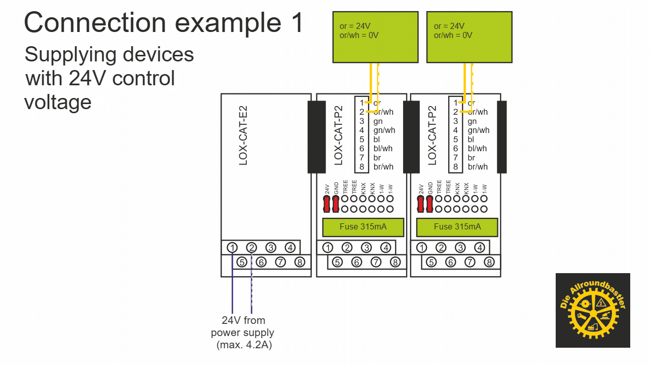
Connection example 1: supplying devices with 24 V DC control voltage
The LOX-CAT-E2 feeds in 24 V from the power supply (max. 4.2 A). Each LOX-CAT-P2 passes it on to the device via the cores or (24 V) and or/wh (0 V), protected with 315 mA.
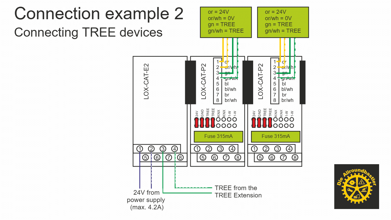
Connection example 2: connecting Loxone Tree devices
In addition to the 24 V, the cores gn and gn/wh carry the Tree bus from the Tree Extension to the Tree devices in the room.
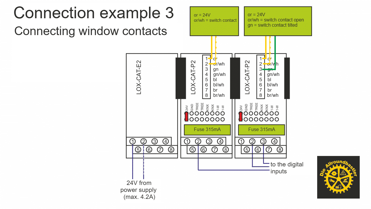
Connection example 3: connecting window contacts
The window contact receives 24 V via or, the switching contact returns via or/wh, and for tilt detection additionally via gn. From the LOX-CAT-P2 it continues to the digital inputs.
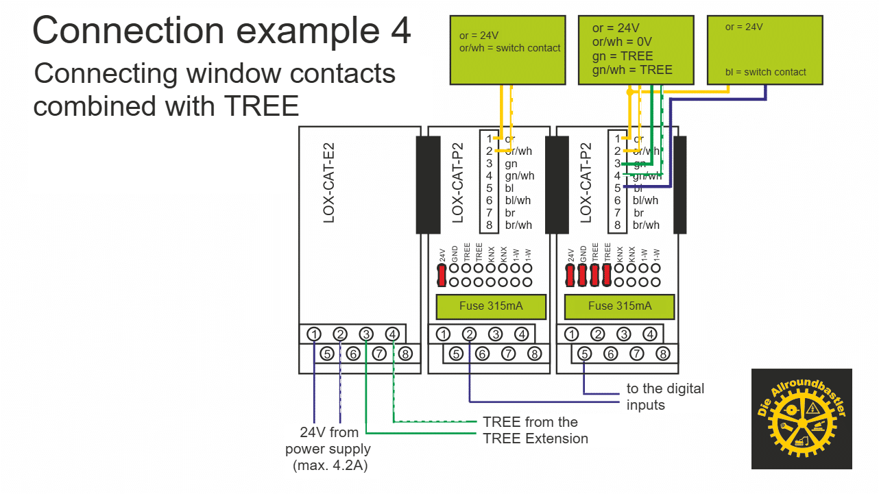
Connection example 4: connecting window contacts in combination with Loxone Tree
Window contact and Tree device on one cable: Tree runs via gn and gn/wh, the switching contact via another core to the digital inputs.
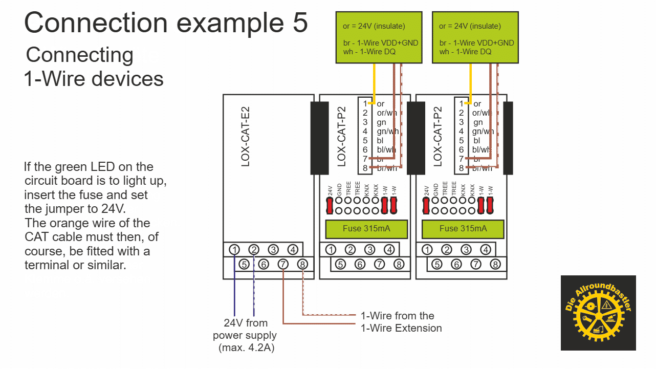
Connection example 5: connecting 1-Wire devices
1-Wire sensors are connected with VDD and GND to br and with DQ to wh; the signal comes from the 1-Wire Extension. The 24 V core or is insulated. If you want the green LED on the board to light up, insert the fuse and set the jumper to 24V.
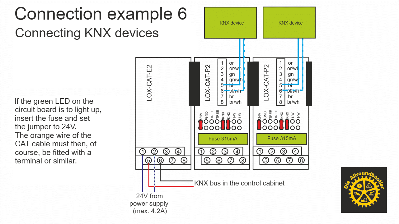
Connection example 6: connecting KNX devices
The KNX bus from the control cabinet runs via bl and bl/wh to the KNX devices in the room. Here too: for the green LED, insert the fuse and set the jumper to 24V.
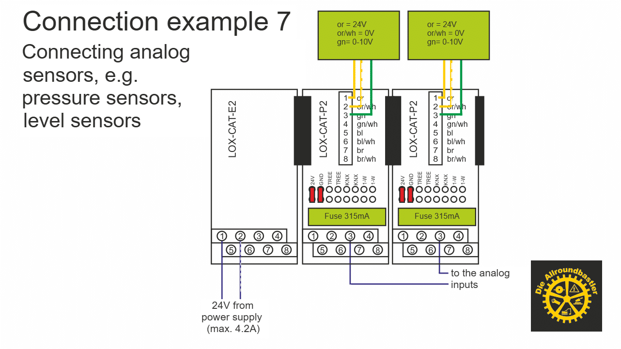
Connection example 7: connecting analogue sensors (0–10 V)
Analogue sensors with 0–10 V, for example pressure or level sensors: 24 V via or and or/wh, the measuring signal via gn to the analogue inputs.
Loxone Config / Loxone info
Templates and documents for Loxone Config: the integration of the Xiaomi robot vacuum, our equalizer recommendations for the Audio Server and everything about the Modbus integration of the Swentibold EuroAir ventilation unit.
- Related:
- Instructions: integrating the ioBroker Xiaomi vacuum cleaner into Loxone
- Video (in German): Swentibold EuroAir via Modbus part 1
- Video (in German): Swentibold EuroAir via Modbus part 2
Xiaomi MiRobot (v1 or S5) integration in Loxone (from Loxone Config 10.0.9.24)
ZIP file for integrating the Xiaomi robot vacuum (v1 or S5) into Loxone, created for Loxone Config version 10.0.9.24 and later. We describe the integration via ioBroker in separate instructions.
Equalizer recommendations for the Loxone Audio Server
Our equalizer settings for the Loxone Audio Server as a PDF.
Loxone Modbus template for the Swentibold EuroAir ventilation unit
To go with our videos “Einbindung Lüftungsgerät Swentibold EuroAir via Modbus” (integrating the Swentibold EuroAir ventilation unit via Modbus) part 1 and part 2 on YouTube (in German). How it works: unzip the ZIP, start Loxone Config, then Insert Modbus device › Predefined devices › Import template.
Swentibold EuroAir Modbus documents part 1
Modbus documents for the Swentibold EuroAir ventilation unit, part 1 – to go with our videos part 1 and part 2 (both in German).
Swentibold EuroAir Modbus documents part 2
Modbus documents for the Swentibold EuroAir ventilation unit, part 2 – to go with our videos part 1 and part 2 (both in German).
Swentibold EuroAir installation instructions
Installation instructions for the Swentibold EuroAir ventilation unit.
Fun: room icon for the Loxone app
Bedroom icon 2
Room icon “Bedroom” for the Loxone app, as a PNG with 32 × 32 pixels.
Control cabinet construction: wiring colours
Wiring colours Loxone control cabinet
Which core colours and cross-sections we use in the Loxone control cabinet: for example 24 V+ dark blue, 0 V blue/white, Tree white and green, Link red and brown, 1-Wire grey and sockets and lights 230 V black with 1.5 mm². Plus the feed-in, neutral conductors and external voltages.
Loxone Energy Meter: connection with current transformers
Loxone Energy Meter connection with current transformers
Wiring diagram for the Loxone Energy Meter on three phases (L1, L2, L3) with current transformers and B6A protection.
Commands and integration of the eDufti kit
- To the products:
- eDufti kit
- eDufti kit individual parts
eDufti kit – integration instructions – version V2
Setup in the Tasmota interface (GPIO assignment and rule for control) and the commands you use to switch the eDufti via ioBroker or directly from Loxone. 2 pages.
Connection diagram / terminal plan ALL-ADA-0-10V-WLAN
- To the product:
- Kit adapter 4x 0-10V to WLAN
Kit ALL-ADA-0-10V-WLAN: terminal and connection assignment
Terminal assignment of the adapter: 24 V supply, sensor supply and the four 0–10 V inputs (AI1 to AI4).
Connection diagrams NWSECU
- To the product:
- NWSECU network security box kit
Connection example NWSECU: connecting the Loxone Intercom
Circuit diagram for wiring with the Loxone Intercom: potential-free outputs to the Miniserver, limit switch, external relay output for resetting and the RJ45 connections.
Connection example NWSECU: connecting external devices
Circuit diagram for wiring with other network devices.
Instructions RASPI-19-2
- To the product:
- RASPI-19-2 housing for Raspberry Pi 4
Instructions RASPI-19-2
Instructions for the RASPI-19-2 housing for the Raspberry Pi 4.
Loxberry installation instructions for the Loxberry-19-2 kit
- To the product:
- Loxberry-19-2 housing
Loxberry installation instructions for the Loxberry-19-2 kit
Instructions for installing Loxberry to go with the Loxberry-19-2 housing kit.
Connection diagrams 2xOC-ADA-LOX (open-collector sensors)
- To the product:
- Kit 2xOC-ADA-LOX
Connection diagram open-collector sensors (kit 2xOC-ADA-LOX)
Terminal assignment for two sensors with open-collector output on the digital inputs of the Loxone Miniserver. Important: these inputs usually have to be inverted in Config.
Frequently asked questions
Are the downloads free of charge?
Yes. You can download all connection examples, diagrams and instructions on this page free of charge and without logging in.
May I use the connection diagrams for customer projects?
Yes. You may also use the connection examples, diagrams and instructions from this page for your customer projects.
Where can I find data sheets for Loxone products?
Data sheets, folders and instructions are in the “Downloads” tab of the respective product in the Shop.
Which circuit boards do connection examples 1–7 apply to?
The diagrams show the LOX-CAT-E2 feed board and the LOX-CAT-P2 connection board. They also apply to the LOX-CAT-P2-V2.
I cannot find suitable instructions. What can I do?
Write to us at shop@allroundbastler.de or via the contact form. Ideally, state the product or your order number.
Note: the download counters are only updated every 24 hours.

